Silicone rubber (often called silicone elastomer) is widely used in seals, gaskets, medical components, and consumer goods. Unlike metals or plastics, silicone behaves elastically — it stretches, compresses, and shrinks more during molding and post-curing. Therefore, defining dimensional tolerances for silicone parts requires a different mindset than for rigid materials.
This article explains which tolerance standards apply to silicone rubber molded parts, how to interpret them, what practical tolerances are achievable, and how to communicate them clearly on drawings or RFQs.
Which Standards Apply?
Silicone rubber parts are governed by general rubber tolerance standards rather than plastic or metal ones. The main references are:
- ISO 3302-1: Rubber — Tolerances for products — Part 1: Dimensional tolerances
- GB/T 3672.1-2002: Chinese standard equivalent to ISO 3302-1
- DIN 7715: Older German standard (mostly replaced by ISO)
These documents define tolerance classes (M1–M4) and dimensional limits based on size range and precision requirements.
Tolerance Classes (M1–M4)
| Class | Description | Typical Applications |
|---|---|---|
| M1 | Highest precision | Medical parts, tight sealing components |
| M2 | High precision | Industrial seals, mechanical interfaces |
| M3 | General precision | Standard molded silicone parts |
| M4 | Low precision | Large or soft non-critical items |
🔹 Use M1/M2 for precision fits, M3 for general components, M4 when dimensions are not critical.
Typical Silicone Shrinkage and Compensation
Silicone exhibits relatively high and variable shrinkage during molding.
| Factor | Typical Value / Range |
|---|---|
| Shrinkage range | 1.5% – 3.0% (average ≈2.0%) |
| LSR (liquid silicone) | Lower and more consistent shrinkage |
| Solid silicone (VMQ) | Slightly higher and less uniform |
| Post-cure dimensional change | 0.1% – 0.5% additional shrinkage |
Design Tip: When designing molds, compensate for shrinkage (usually +2%) in the cavity dimension. Document the assumed shrinkage and confirm during the first article inspection.
Practical Tolerance Reference Table
| Nominal Size (mm) | M1 (mm) | M2 (mm) | M3 (mm) | M4 (mm) |
|---|---|---|---|---|
| 0 – 6 | ±0.08 | ±0.10 | ±0.20 | ±0.30 |
| 6 – 10 | ±0.10 | ±0.15 | ±0.25 | ±0.40 |
| 10 – 18 | ±0.13 | ±0.20 | ±0.35 | ±0.50 |
| 18 – 30 | ±0.16 | ±0.25 | ±0.40 | ±0.70 |
| 30 – 50 | ±0.20 | ±0.35 | ±0.55 | ±0.90 |
| 50 – 80 | ±0.25 | ±0.40 | ±0.70 | ±1.10 |
| 80 – 120 | ±0.35 | ±0.50 | ±0.80 | ±1.30 |
⚙️ For very thin parts (<1.0 mm) or soft walls, increase tolerance by ±0.1–0.2 mm.
LSR vs. VMQ (Solid Silicone) Differences
-
LSR (Liquid Silicone Rubber):
- Injection molded
- Excellent repeatability
- Lower shrinkage variation
- Suitable for high-precision parts (medical, automotive sensors)
-
VMQ (Solid Silicone):
- Compression or transfer molded
- Larger variability in shrinkage and surface finish
- Lower cost, suitable for medium-precision parts
Measurement and Inspection Guidelines
Silicone is soft — measurement accuracy depends heavily on conditions. Define them clearly in the drawing or quality document:
- Measurement temperature: 23 ± 2 °C
- Conditioning: Measure after 24 h at room temperature post-cure
- Measurement tools: Soft-jaw calipers, optical projector, or low-force CMM
- Probe force: ≤0.5 N to avoid deformation
- Support method: Measure free-state or under defined compression
- Sampling: Define inspection quantity (FAI 100%, production AQL)
Tip: Document measurement force, fixture, and orientation in the drawing to ensure consistency.
Mold Design Factors Affecting Tolerances
- Mold material & temperature control: Affects cavity accuracy and shrinkage repeatability
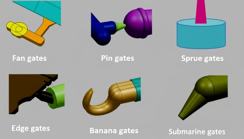
- Venting & gating: Poor venting causes flash and distortion
- Uniform wall thickness: Avoid large thickness transitions
- Post-curing: Stabilizes dimensions; specify time & temperature
- Tool maintenance: Regularly check cavity wear and update measurements
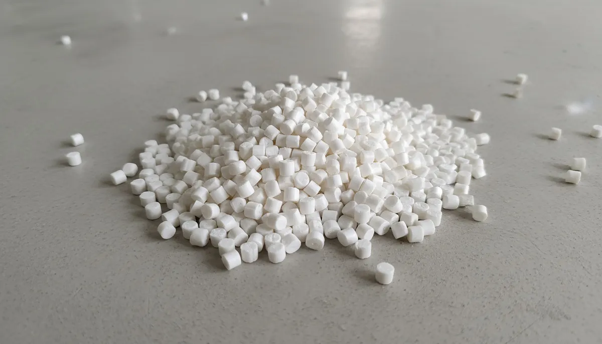
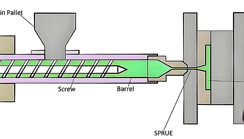
Plastic resin pellets used in injection molding
Surface and Feature Recommendations
- Avoid sharp corners; use 0.5–1.5 mm radii
- Keep text height ≥0.5 mm, line width ≥0.5 mm for readability
- For ribs and thin walls, minimum thickness should be 0.8 mm (for 50A silicone)
- Avoid deep undercuts unless absolutely necessary

Injection molding machine in production
How to Specify Tolerances in Drawings / RFQs
Always include these details when creating a drawing or purchase order:
- Tolerance class per dimension: e.g.
Ø30.00 ±0.20 mm (ISO 3302-1 M2) - Material & hardness:
Silicone VMQ 60 Shore A - Process:
Compression moldedorLSR injection molded - Shrinkage assumption:
2.0% compensated in mold - Measurement conditions: Temperature, post-cure, tools, probe force
- Surface finish: If required, define Ra or texture code
- Inspection requirement: FAI or batch sample plan
Example Drawing Note: Material: LSR, 50 Shore A Tolerance: ±0.10 mm (ISO 3302-1 M2) Measurement at 23 ± 2°C after 24h post-cure Assumed shrinkage 1.8% compensated in cavity Process: Injection molded
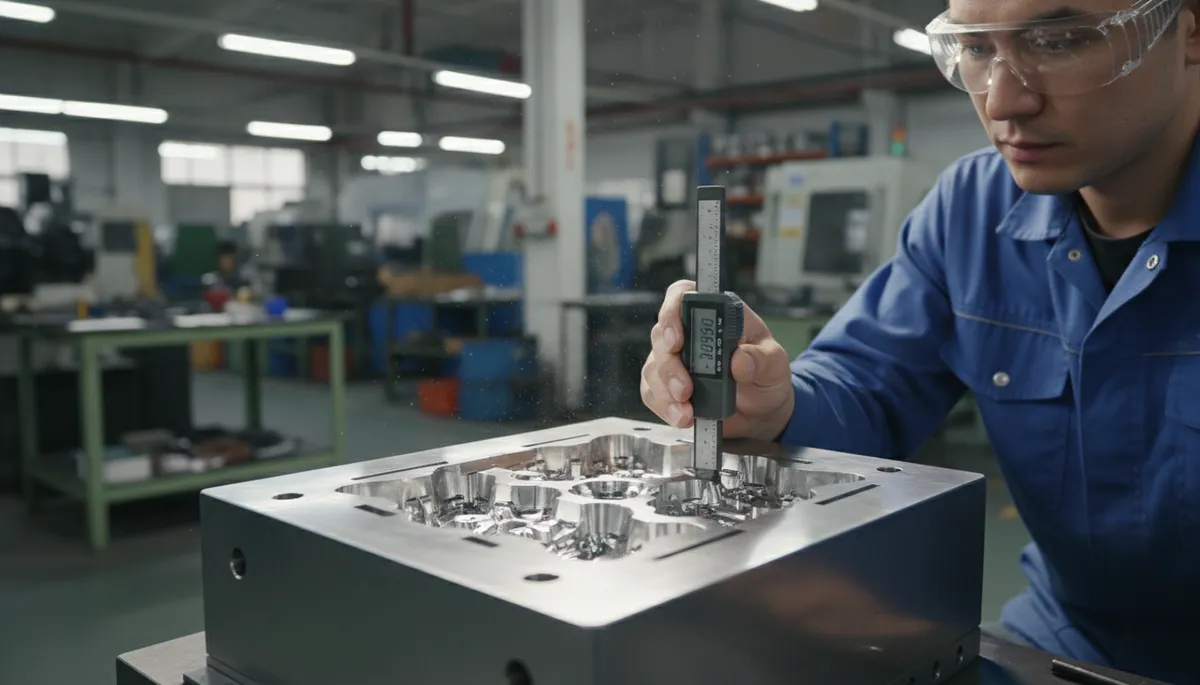
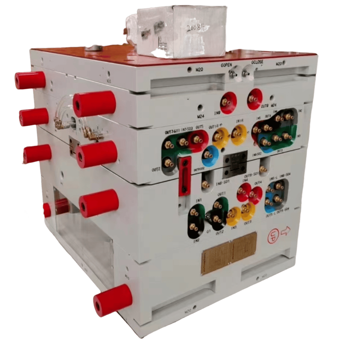
Precision mold tooling inspection and measurement
Inspection and Statistical Control
- First Article Inspection (FAI): Verify key dimensions before mass production
- Process Capability (Cpk/Cp): Track for high-volume precision parts
- AQL Sampling: For non-critical items
- Control Charts: Monitor key features (ID/OD, thickness)
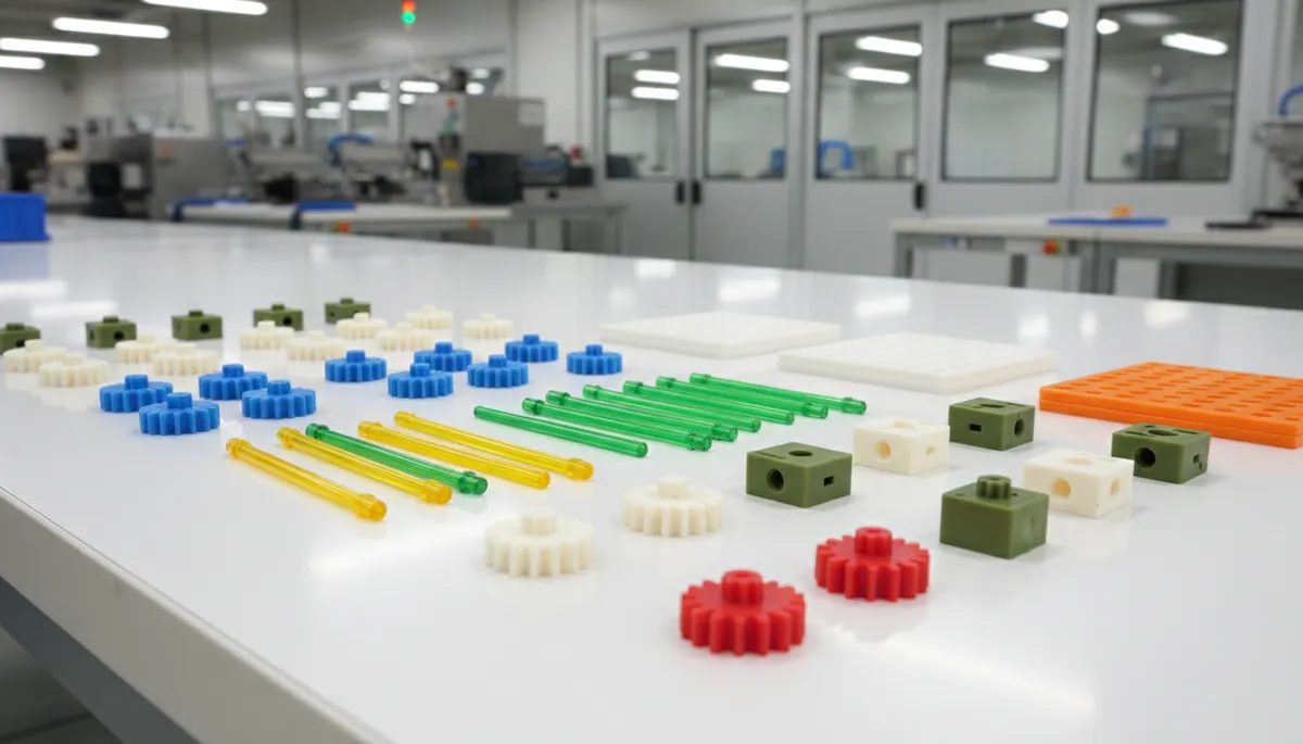
Batch of injection molded plastic parts
Common Pitfalls and Fixes
| Pitfall | Cause | Solution |
|---|---|---|
| Expecting plastic-level tolerances | Silicone elasticity | Apply ISO 3302-1 (M1–M4) appropriately |
| Measurement inconsistency | Undefined method | Specify temperature and probe force |
| Post-cure shrinkage not considered | Material relaxation | Measure after full post-cure |
| Thin flexible geometry | Design oversight | Reinforce ribs, add fillets |
Case Study: Precision Silicone Seal
Part: LSR gasket for automotive sensor Material: LSR, 50 Shore A Process: Injection molding Specified: ID Ø20.00 ±0.10 mm (M1), OD Ø24.00 ±0.15 mm (M2) Post-cure: 2h at 200°C Result:
- Actual shrinkage 1.6%
- Mold cavity adjusted after FAI
- Cpk = 1.67 achieved after tuning
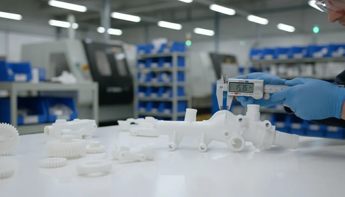
Quality inspection of injection molded plastic parts
Frequently Asked Questions
Q1: Can silicone parts reach ±0.05 mm tolerance? Only for very small, rigid features or LSR parts with strict process control. Normal ranges are ±0.1–0.3 mm.
Q2: Should I define tolerances for every dimension? No. Apply general notes like “Unspecified dimensions per ISO 3302-1 M3” and specify tighter tolerances only where critical.
Q3: How to specify compressed dimensions for seals? Define the functional dimension under compression, or add a note like “Measured at 5% compression.”
Conclusion and Checklist
To ensure successful silicone rubber part production:
- Choose the correct tolerance grade (M1–M4).
- Specify material, hardness, and curing type.
- Define molding process (LSR, compression, transfer).
- Document shrinkage assumption.
- State measurement temperature and tools.
- Require FAI and define sample plan.
- Avoid unrealistic plastic-level tolerances.
- Maintain tooling and process stability.
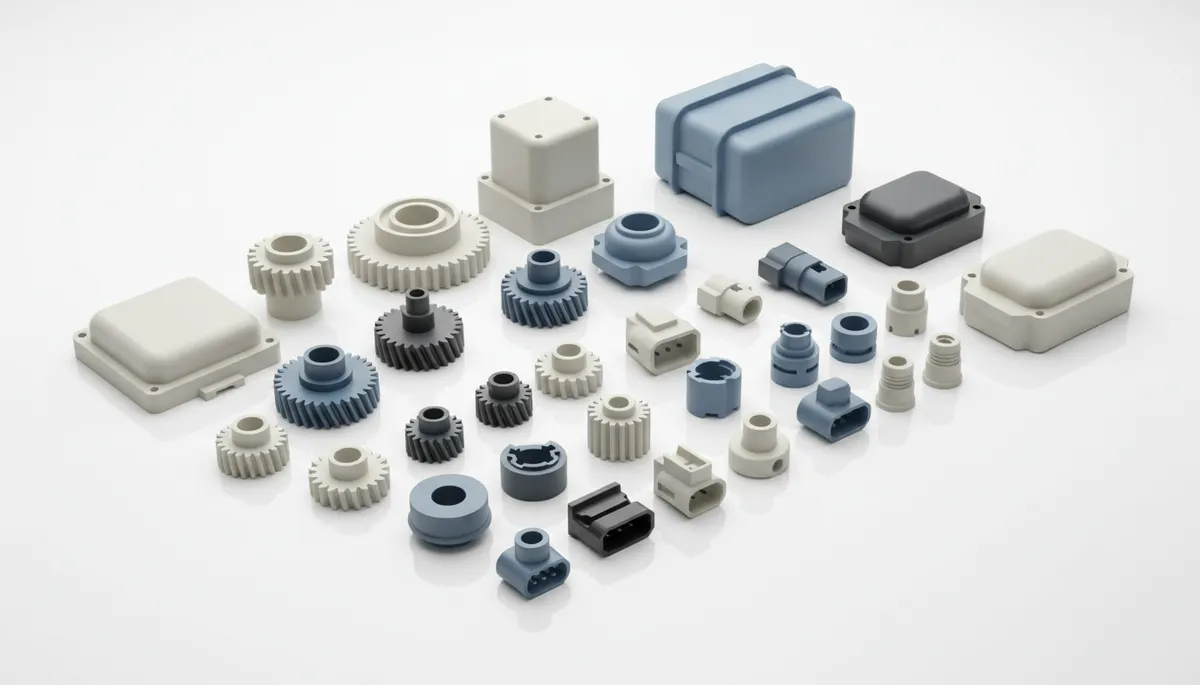
Various injection molded plastic parts
Appendix — Quick Reference
Standard: ISO 3302-1 / GB/T 3672.1 Shrinkage: 1.5% – 3.0% (design baseline 2.0%) Tolerance Classes: M1 (Highest) / M2 / M3 / M4 (Lowest) Measurement Temp: 23 ± 2 °C Post-cure: Measure after full cure LSR: Better repeatability than compression molding
Author’s Note: This guide is part of our Silicone Molding Knowledge Series, written to help engineers and buyers define achievable, industry-standard tolerances for silicone products.
Need a Quote for Your Injection Molding Project?
Get competitive pricing, DFM feedback, and production timeline from ZetarMold’s engineering team.
Request a Free Quote → See our Injection Mold Complete Guide for a comprehensive overview.